Networking III - Routing, DNS
At this point, you can already set up simple network configurations. This week, we will continue exploring networking commands - in particular those related to routing - and we will interact with a basic Domain Name System (DNS) and web server.
Learning Goals
After this lab you will be able to:
- Recognize the role of routing in networking
- Use
ip routefor managing routes - Retrieve basic DNS information
- Deploy simple network services
Lab Exercises
Please read each exercise entirely before starting to solve it.
Remember that you should deliver a report after the networking module is finished. It should include the main commands and configurations necessary to complete each exercise. Do not forget to take notes while solving the exercises so you do not have to repeat them.
These exercises should be completed in teams.
Import and Topology
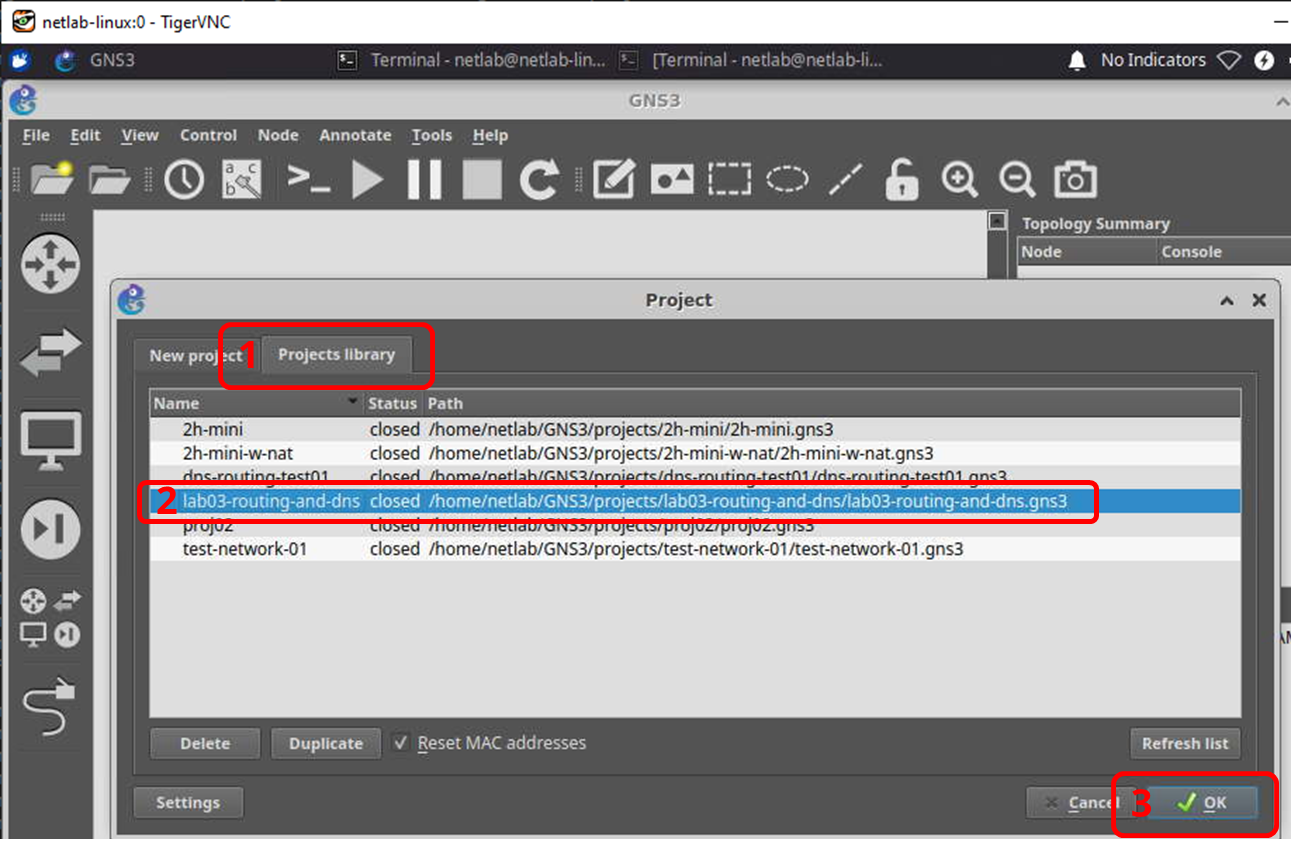
For today's lab, we're going to use a project that comes with several pre-configured components. To get started and make sure that changes are applied within GNS3, close any running instances of GNS3 and launch it again. On launch, pick the lab03-routing-and-dns project from the Projects library tab in GNS3 as outlined in the following graphic.
You will be presented with a network topology that consists of three routers (R1-R3), a switch, and three hosts, corresponding to a client, a DNS server, and a (web) server. A schematic overview of the network topology is provided in the graphic below. The graphic shows network interface names alongside their configured IP addresses, their interconnections, and uses the same colors to highlight interfaces that are on the same subnet.

Identifying Packets' Paths and Confirming Routes
The hosts and routers are already set up in a way that allows communication between the client (10.240.1.3) and the server (10.168.1.2). First, confirm that this is actually the case - for instance by ping-ing from one to the other. Although this confirms connectivity, you do not yet know which path packets take through the network to reach their respective destination.
- Recall (or look up online) which command line tool we used to figure out the path packets take to a given destination and use it to determine the sequence of IP addresses / interfaces / devices that packets from the client take on their way to the server.
The way packets are treated by computers and routers along the way is determined by the devices' routing tables. You can inspect routing table entries by issuing the ip route command. For instance, the routing table of the client looks as follows:
root@client:/# ip route
10.168.1.0/24 via 10.240.1.1 dev eth0
10.240.1.0/24 dev eth0 proto kernel scope link src 10.240.1.3
root@client:/# ip route
10.168.1.0/24 via 10.240.1.1 dev eth0
10.240.1.0/24 dev eth0 proto kernel scope link src 10.240.1.3
The first item of any routing table entry is the destination network (10.168.1.0/24 and 10.240.1.0/24 in this example). If the device wants to send a packet towards the specified network, it will consult the matching routing table entry to find the appropriate interface to send it out of and the next-hop device (typically a router) along the way.
In case of the first rule, packets destined for the 10.168.1.0/24 will be sent out the eth0 interface towards the eth0 interface of router R1 which is on the same network as the client and has the IP address 10.240.1.1.
The second rule states that if the client wants to send data to any device in the 10.240.1.0/24 network, it shall use the eth0 interface and use 10.240.1.3 as its source IP address.
- Using the
ip routecommand on the routers you identified along the path from client to server, confirm that the route configuration does indeed match the observed behavior. In particular, explain which routing table entries are triggered when a packet from the client to the server or a packet from the server to the client traverses the respective router.
Adjusting Routes
In addition to retrieving routing table information, the ip route command can be used to modify routing behavior. Using the same syntax as the outputs we discussed in step 1, we can use ip route add and ip route del to add or delete entries. For instance, you can delete the route to the server from the client to the server by ip route del 10.168.1.0/24 via 10.240.1.1 dev eth0.
- What happens if you try to ping or otherwise reach the server after deleting the route? Add the route again and confirm that connectivity is restored.
- Using your knowledge of routing and the
ip routecommand, adjust the routing table entries on routers R1, R2, and R3 so that packets from the client to the server take the path client-R1-R2-server. Document and discuss the purpose of all commands and where you use them, and finally confirm your configuration by once again checking the output of the tool for checking the end-to-end path on the client.
For this step, you will only need rules of the shape <destination_network/mask> via <next_hop_ip> dev <interface>.
If your configuration happens to break along the way, you can just restart the device in question or the entire network to revert it back to its initial configuration. If restarting the device(s) from within GNS3 does not resolve the issue, you can also exit and restart GNS3.
DNS Server and Client-Side Nameserver Settings
To get started with this step, let the server machine run its web server in the usual way.
root@server:/# cd /var/www/
root@server:/var/www# python3 -m http.server 80
Serving HTTP on 0.0.0.0 port 80 (http://0.0.0.0:80/) ...
root@server:/# cd /var/www/
root@server:/var/www# python3 -m http.server 80
Serving HTTP on 0.0.0.0 port 80 (http://0.0.0.0:80/) ...
From the client, confirm that you can download the web site from the server with curl 10.168.1.2.
Our goal for this part is to use DNS to enable the client to reach the server through the more human-readable address ttm4175.com rather than its IP address.
Open a console on the dns host and navigate to /etc/bind. This is the home of configuration files related to the BIND 9 DNS server that runs on this host.
- Inspect the file
named.conf.local. Thezonedefines the portion of the namespace for which this machine is responsible. Inside the zone definition,filepoints to the file that contains the actual DNS records for the zone. Use the BIND 9 documentation or any other source to find the meaning of thetype masterpart of the configuration.
- Take a look at the
filethat is referenced in the above configuration. Go through the file and discuss the broad meaning of the various entries. Feel free to consult online resources.
- You can make DNS requests from the client to the DNS server by invoking the
nslookuputility that we used in the past. Issue the commandsnslookup ttm4175.com,nslookup ttm4175.com 10.240.1.2, andcurl ttm4175.comat the client. Explain the different outputs you get.
- Back in GNS3, start a capture on the link between the client and the switch. Re-run
nslookup ttm4175.com 10.240.1.2and discuss the DNS packets you see. What transport protocol does DNS use? What kinds of and how many queries and responses are being sent?
- To add our DNS server as the default nameserver for the client, open a console on the client and use a text editor such as
nanoto add the following line to/etc/resolv.conf:
nameserver 10.240.1.2
nameserver 10.240.1.2- Run
nslookup ttm4175.comandcurl ttm4175.comagain and document what happens.
End-to-End Scenario
- For your report, describe what happens in the network when you download the page "ttm4175.com" (e.g., when you use
curl ttm4175.com). You can explain, step by step, the requests and answers from the client to the server and back. This should include the IP addresses, protocols, and involved devices / services. You can also provide screenshots to illustrate and highlight your explanations.